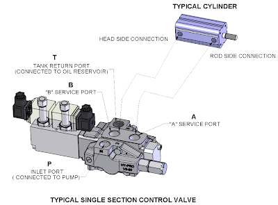
STEP 1
The first step in designing a hydraulic system is to select a suitable pump & actuator, this will determine the flow required and the operating pressure.
STEP 2
The next task for the designer is to select the most suitable control valve to operate the function(s). The most economic solution is dependant on the application duty cycle & number of functions.
INTERMITTENT OPERATION: In systems which are required only intermittently, e.g. 2 or 3 times a day for short periods, a smaller valve (cheaper) with higher pressure losses would be acceptable.
FREQUENT / CONTINUOUS OPERATION: Systems which are used frequently or continuously mean energy losses are of greater concern and a larger size valve would be preferable. This reduces energy loss, saves on energy bills and reduces heat input to the oil. This could eliminate the requirement for larger reservoirs & oil coolers.
NUMBER OF FUNCTIONS: Open Centre control valves can be built to operate more than one function by adding spools to the valve bank. The greater the number of spools in the bank, the higher the pressure losses. Consequently it may be necessary to increase the valve frame size to give acceptable pressure losses.

(Click on image to enlarge)
The above diagram represents a simple hydraulic circuit.
The key performance factors to considered when selecting a valve are:
The key performance factors to considered when selecting a valve are:
- The pressure rating of the valve must be compatible with the system operating pressure.
- The size of valve should be selected to minimise the pressure loss P to T to minimise energy consumption when the system is idling.
- The pressure losses to and from the cylinder ports should be kept to a minimum to maximise the power available to operate the functions. ie Pressure losses P to A/B & A/B to T.
These pressure loss/drop curves are normally available on valve suppliers catalogues. Typical P-T curves shown below.

(Click on image to enlarge)
Visit www.hypro.co.uk/sectional.htm for our own technical information.
